CrossFill: Foam Structures with Graded Density for Continuous Material Extrusion

Next week I will be presenting our latest paper called “CrossFill: Foam Structures with Graded Density for Continuous Material Extrusion” at the Symposium on Solid and Physical Modeling which is part of the International Geometry Summit.

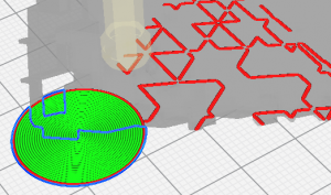
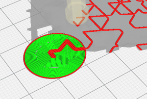
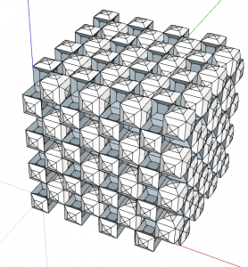
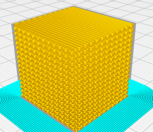
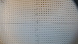
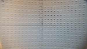
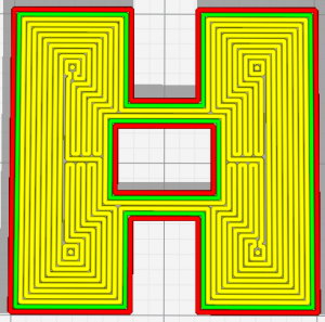
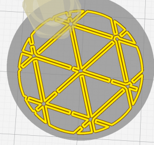
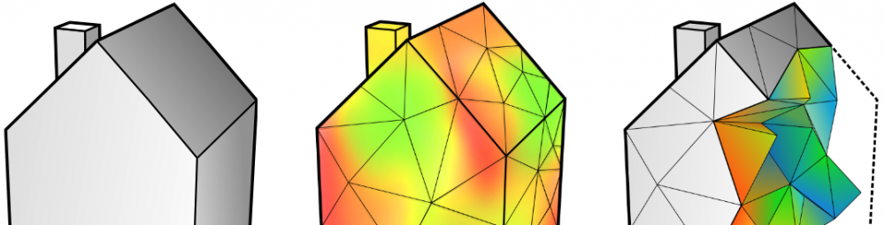
We present an infill structure which satisfies a user-specified density field in order to generate infill with densities which gradually change throughout the object.
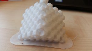
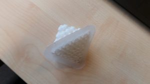
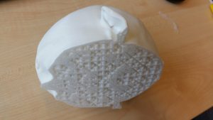
The infill pattern is very compliant and when you print these infills using a flexible filament such as TPU, the structures behave like a foam.
[youtube]https://youtu.be/lcLcsprxIHw[/youtube]

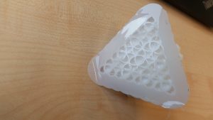
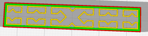
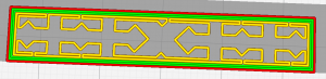
There are also some options in Cura to ensure that the infill structure has an almost fully connected channel of air inside – just like gyroid infill does.
However, in my latest implementation I had to remove these features, because the expanded functionality of following a user-specified density distribution couldn’t support the idea of keeping connected air channels inside.

Homogeneous CrossFill is already incorporated in Cura, but some of the features I present here are not yet incorporated.
The infill pattern has become the industry standard for printing with TPU by now.

The paper can be accessed for free for a limited amount of time via the this link.
Otherwise you can access the pre-print here.

Custom build plate adhesion

I was playing around with some complex custom infill patterns and when trying to print it I noticed that it would be hard to print without a brim, but the prim would be very hard to remove after printing, because of all the complex geometry in the 3D model.
I therefore decided I should add custom platform adhesion in Cura.

I loaded in a model of a cylinder and changes its height to the initial layer height.
Then in the per-object settings I set the top/bottom pattern to concentric.
Some people call this technique ‘mouse ears’ – as a reference to the familiar Disney character perhaps.

However, now my custom brim was replacing my model, instead of being printed around the model like you would expect for an adhesion brim or skirt.

I therefore submitted a pull request to the Cura team to let the user be able to influence which part gets precedence of which when removing mesh intersections (carving multiple volumes). I’ve renamed the setting Infill Mesh Order to Mesh Processing Rank and made it so that the same setting is also used when processing the order of normal meshes. The functionality is actually quite the same as for infill meshes.

With the updates to Cura the result can now be configured to look like this:

Let’s hope it will be incorporated in Ultimaker Cura soon!

link to the official pull request

Wavy cube infill

I came up with this way to make cubic infill but instead every cube has 3 convex faces and 3 concave faces.

Every layer could be printed with wavy lines, but in my prototype they were printed as separate line segments and the ordering wsa not efficient.

I printed them in TPU.

Conclusion: there is not much merit in this type of infill structure.

Designing voxel models

Designing volumetric propertiea is quite a difficult task in the current software culture. None of the standard CAD programs work with volumetric specifications (in my limited experience).

Gladly there is Autodesk Monolith. You can import an STL, which is converted into a voxel field with densities of 100% inside the STL and 0% outside.

You can then model your properties by painting the voxel colors; you need to uncheck geometry so that you only affect the voxel colors, not the densities.

Set the visualization alpha really low so that you can easily see what’s going on inside the model.

When you’re ready go to the rasterization tab and select to only export the material ratio. You can then export the voxel model to a sequence of images. The image lightness encodes the material ratio and the alpha channel encodes the material density.

This is a really nice tool if you want to draw volumetric material property specifications. It can be used to specify an image sequence to be used in Cura as a density voxel model for 3d printing with FDM.

Support Brim

Last week I started a print in TPU with PLA support, but the support failed because it doesn’t adhere to the brim which I printed in TPU.

To fix my print I used hotglue to (melt the support and) glue the support to the brim. That hack worked!

In the meantime I decided that this behaviour should be improved. I wrote a feature which replaces the regions under support with a brim printed in the same material as the support. That way the adhesion of the support to the buildplate is improved and the brim region next to the object is still satisfied – albeit with 2 different materials.

Robust Connect Infill Polygons

The features to connect infill polygons together in order to get continuous extrusion for all infill patterns was not very stable. It is quite hard to reliably find a location where you can cross to another polygon and it often happens that that crossing doesn’t permit a crossing back, so that the bridge between two polygons cannot be created. The implementation is now improved.

Whereas it used to connect 65% of all polygons before it now connects 99.5%.

Hopefully this improvement can be merged to Ultimaker Cura shortly.

Big gray scale project

Today I had a talk with Alessandro Sambini, Joris v Tubbergen and others about an art project which is centered around creating a life-size statue of a person using my gray-scale halftoning technique.

We need to do some initial experiments to see how well the techniques adapt to higher layer heights and bigger nozzle sizes to see whether the project will go through, but I have full confidence.

Permeable prints

In some cases you might want a 3D print with a very permeable structure. For example when using a 3D print as a mold for vacuforming, the permeability is used to transport the air out. Another example is when combining 3D printing materials with casting materials; in order to optimize the adhesion between the two materials, the casting materials permeates a bit into the 3D printed structure.

There are several ways in which to create such a structure. In this post I describe one which consists of a couple of simple Cura settings.

The idea is to print the whole object with infill only, so we set the Top/Bottom Thickness and the Wall Thickness to zero.
Then we set the Infill Pattern to Zig Zag and the Infill Density to 50%.

Now here’s the catch: we set the Infill Line Directions to [ 0,0,0,0,0,0,90,90,90,90,90,90 ]

We end up with a print which is rather porous and has little resistance to air flow.

I’ve printed one with TPU. Here’s the result.
Top:

Side:

Voxel models

Cura now supports voxel models, by loading in a sequence of images if the first image ends in a number.

The XY are stretched so that the object fits inside while the XY ratio is maintained.
The Z of the images is independently stretched so that all images cover the whole 3D model.

I’ve used it to create some prints which are based on DICOM files from CT-scans.

Note that the surface model is extracted from the DICOM files in a separate program (3D slicer).
I converted the DICOM files into standard png images using MATLAB.

Then I converted the images such that the highest density equaled the density I had set in Cura and a cropped them to where the surface model reached.

This is the result:

This is a sample MATLAB code:


files = dir('osseux/*.dcm');
for file = files'
path = strcat(file.folder, "/", file.name);
a = dicomread(path);
min_val = 300.0 / 32768.0 + .5;
max_val = 1800 / 32768.0 + .5;
minn = min(min(a));
maxx = max(max(a));
a_mapped = uint16(int32(a) + 32768);
adjusted = imadjust(a_mapped, [min_val max_val], [0.0 1.0], 1.2);
[filepath,name,ext] = fileparts(file.name);
outfile = strcat(file.folder, '/output/', name, ".png");
imwrite(65535 - adjusted, outfile{1});
end

Don’t blame me if this crappy hacked together code doesn’t work on your machine! 😉

Here’s a sample converted .cdm file: